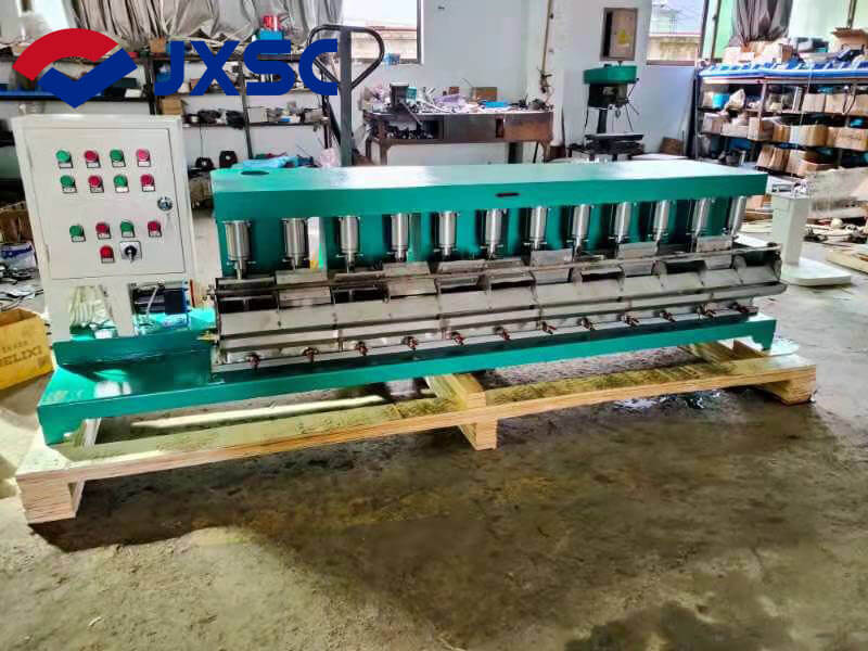
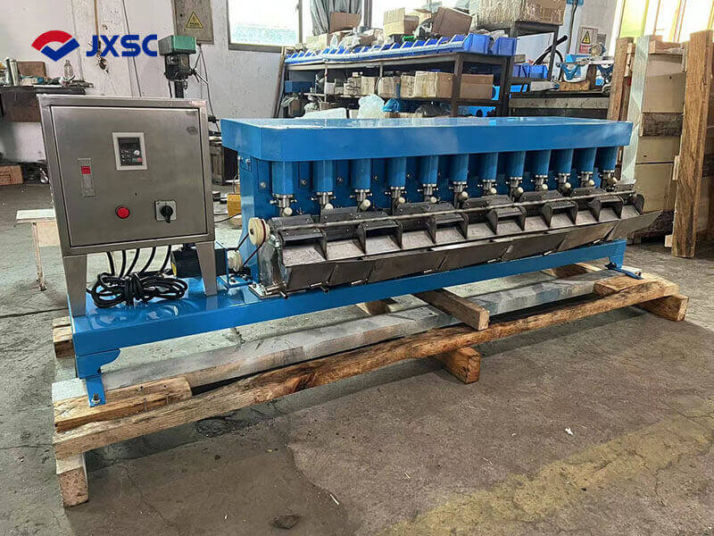
The FX-type mechanical continuous flotation machine is suitable for laboratory mineral separation through flotation methods. This flotation machine is a continuous-stirring lab flotation machine connected in groups of two or more cells. The number of cells is even, ranging from two to ten, and can be left or right according to the user’s requirements.
Technical Parameters
Model specifications Unit FX2-24
Tank capacity L 24
Numbers of cells cell 2
Impeller diameter mm Φ170
Impeller speed r/min 0-800
Scraper speed r/min 15、30
Feeding size mm ≤0.2
Motor(set/2tank) w 1100
Overall size mm 970×900×960
Weight KG 240
Structural Description
The FX-type flotation machine belongs to the impeller-type mechanical agitation flotation machine. It consists of the following major parts: tank body, impeller, main shaft, scraper, frequency converter, and other components.
Flotation Cell System
- To adjust the slurry level in the tank and the thickness of the scraped foam layer, make the two tank wall plates into an intermediate tank with a slurry level regulator. At the same time, installing the perforated plate on the cover of the cell to prevent the chaotic slurry movement from affecting the foam area. It also prevents the gangue from being taken into the concentrate by machinery. The discharge port lies outside the bottom of the tank. It is for draining water during cleaning.
- The slurry flows through the overflow port on the wall panel and enters the middle and tail tanks. The conduit covering the lower part of the middle tank and the lower part of the tank wall enters the next tank, so the slurry can continue to flow through all tanks. It flows into the feed tank and discharges from the discharge port of the tail tank. There are inlet ports at the front and back of the lower part of the tank body, which facilitate changing the process flow.
Impeller System
- The impeller system is a disc impeller installed at the center of the flotation machine cell. The blades are arranged radially upward and fixed at the lower end of the main shaft. A circulating pipe is installed outside the main shaft. The upper end of the pipe lies above the mortar and foam layer, and a slurry suction pipe lies in the middle. The slurry suction pipe is fixed with the cell wall plate by screws, and the lower end is equipped with a protective disk. A backing plate fixes the bottom of the protective disk. When the flotation machine’s impeller rotates, large amounts of air come along the circulating pipe and pump slurry. The gap between the protective disk and the impeller is related to the amount of air inhaled. If the gap is too large, replace the worn backing-plate, or adjust it properly.
- The hole on the upper part of the circulation tube is to circulate the slurry and mix it with air. The upper part of the impeller shaft is installed in the rolling shaft inside the bearing housing to rotate. The bearing housing is installed on the crossbeam. The top of the shaft fits with a pulley connected to the motor through a V-belt for rotation. Adjust the tension of the V-belt motor seat to achieve the purpose.
Foam Scraping Device
The foam scraping device uses a rotary scraper to lift the foam along the flotation machine. The scraper is installed on the ore discharge opening of the tank body. One end of the scraper shaft installed a belt pulley, which drives it through the belt pulley.
Operation And Installation
Operation of FX Mechanical Continuous Flotation Machine
- Check if the flotation machine is damaged and rotate the main shaft to see if it is flexible and not stuck.
- When connecting the power supply and motor wiring, pay attention to the clockwise direction of the spindle rotation.
- During flotation, the motor drives the main shaft and impeller to rotate through the triangle belt for pulp mixing, and the scraper motor drives the scraper device to rotate. The scraper makes foam flow out to the tank mouth. The liquid level and the height of the foam layer are controlled by the rise and fall of the level regulator of liquid. After flotation, pull out the plug at the bottom of the cell, and discharge the residual waste liquid inside the tank.
- Adjust impeller speed: Control the impeller speed by adjusting the frequency converter knob.
- Adjust the scraper speed: Loosen the fixing screw of the scraper motor, adjust the V-belt to another slot, tighten the belt, and then fix the fixing screw to the bracket.
Installation of FX Mechanical Continuous Flotation Machine
- Install the machine on a worktable. When operating the flotation machine continuously in four or more slots, all table groups must be on the same horizontal plane, and the scraper shaft should connect on the same straight line. There should be no leakage at the connection of the table group.
- The installation location of the machine must have a 220/380V AC power supply. When wiring the motor, pay attention to the vertical axis rotation direction and turn clockwise.
Maintenance And Upkeep
- Regularly check whether all fasteners are loose.
- Before starting work, it is necessary to check whether there is anything in the groove that has stuck the spindle, any noise during operation, and any leakage or other faults in the sealing device. If find any abnormalities, stop the machine for maintenance in time.
- After finishing the experiment, clean and wipe all parts till dry.
- Add oil through the grease nozzle on the main bearing seat. Do not add too much oil to avoid leaking into the flotation tank and affecting the slurry.
- Add concentrated engine oil to the scraper shaft before each operation.
JXSC lab mineral processing equipment manufacturer has more than 38 years of experience in mining processing. We provide various lab mining equipment including gravity-separating equipment for processing minerals such as gold, tin, tungsten, lead, zinc, tantalum, niobium, iron, manganese, silver, titanium-iron, etc. Lab machines include laboratory jaw crusher, hammer crusher, roller crusher, grinding equipment, lab gravity separator, screening, washing equipment, etc. Welcome to consult!

